
Bearing starting Torque Measurements Down to -100°C
Bearings are used in the mechanisms that will deploy the REASON antennas. These antennas use stored strain energy in springs to provide the motive force that deploys the antennas. These antennas are designed, fabricated and tested mechanically by Heliospace Corp. in Berkeley, California under a subcontract to NASA/JPL. During deployment of the antennas, the temperature may be as low as -70°C.
There is a limited amount of data available regarding potential lubricants for operation at such low temperatures. Extrapolation of this data indicated that they could potentially provide the desired lubricating action, but the uncertainty was high so testing was performed to confirm the behavior of the lubricants at these temperatures. At low temperatures, the viscosity of lubricants can increase by orders of magnitude.
Because oil does not crystallize, or solidify, at any temperature, it technically does not freeze. However, at low enough temperatures it will lose its liquid-like properties and not flow enough to provide adequate lubrication.
It was possible that the spring force available in the actuators would not be sufficient to overcome the low- temperature bearing resistance. We were confident that if the bearing was able to start turning, the shearing action in the lubricant would warm it locally, decreasing its viscosity, allowing the rolling action of the bearings to continue reliably. Therefore, we focused on measuring just the starting torque at various cold temperatures.

These experimental measurements confirmed that the available mechanism torque was well above the measured starting torque even at temperatures that were colder than our expected worst-case cold deployment conditions. In addition, the testing confirmed that the volume of lubricant selected was appropriate for the short-duration one-time operation of the devices containing the tested bearing types. In the body of this paper, we describe the three bearings tested, indicate the lubricant selected, illustrate the test apparatus, and present the results of starting torque versus temperature.
Bearings Tested
We tested three bearings of the type selected for use in the design of the mechanism. Our colleague, Mark Balzer, named them Papa Bearing, Mama Bearing, and Baby Bearing because of their relative sizes. We fondly retained this nomenclature.
The three bearings tested are:
- AST 07150776 (SSRI-1212ZZRA5P25L01 BEARING; MINO: 00585 X 74748) Approximate bearing dimensions: 19.05 mm outer diameter (OD) x 12.70 mm inner diameter (ID) x 3.94 mm width (W) (0.750 inch x 0.500 inch x 0.155 inch) (Papa bearing)
- AST 07366778 (SSR3ZZRA5P25L01 INCH SERIES BEARINGS; MINO: 00585 X 00208) Approximate bearing dimensions: 12.70 mm OD x 4.70 mm ID x 4.95 mm W (0.500 inch x 0.185 inch x 0.195 inch) (Mama bearing)
- AST 07366756 (SSR2ZZRA5P25L01 INCH SERIES BEARINGS; MINO: 00585 X 00187) Approximate bearing dimensions: 9.53 mm OD x 3.05 mm ID x 3.96-mm W (0.375 inch x 0.120 inch x 0.156 inch) (Baby bearing)
Manufacturer – New Hampshire Ball Bearing, Inc
Ring material – AISI 440C
Ball material – AISI 440C
Type – Radial
Shields – Double metallic shield, removable
Cage – Ribbon, land piloted
ABEC tolerance – ABEC 5
Radial play – 0.005 mm to 0.013 mm (0.0002 inch to 0.0005 inch)
Prior to testing, the bearings were inspected and passed per the following criteria:
- Surface Appearance:
- Lands, faces and mounting surfaces of bearing assemblies shall have a smooth finished appearance.
- The surfaces shall be free of visible tool marks, chatter and waviness, pits, scratches with raised metal, or other surface imperfections.
- Metal bearing components shall have a smooth finished appearance and shall be free of burrs, dents and folded material.
- Non-metallic bearing components, including retainers, cages, and separators, shall be free of delaminations and burrs.
- Cracks and fractures:
- All bearing assemblies shall be free of cracks and fractures.
- All bearing assemblies shall be free of scratches on critical surfaces.
- All critical surfaces of bearing assemblies shall be free of scratches.
- Contamination:
- All exterior surfaces and interior areas of the bearing assemblies shall be free of foreign objects and debris, particles, fibers, grease, oil, fingerprints, etc.
- Corrosion:
- All exterior and interior surfaces of the bearing assemblies shall be free of corrosion, rust, and stains.
- Assembly:
- The proper number of rolling elements shall be present.
- Retainers, cages, and separators shall be of the proper type (inner land-/outer land-/ball- guided), made of the proper material, and shall be installed in the proper orientation.
Lubricant
The bearings are commercial off-the-shelf. Their standard lubricant is not suitable for use at the low temperatures possible for this mechanism. After considering the potential operating conditions, we decided to remove the lubricant in the bearings and replace it with Castrol Brayco 815Z Micronic Grade Oil – a clear water white perfluorinated polyether-based fluid. We also selected alternate lubricants, but did not test them because our first choice was demonstrated to operate as desired.
The bearing retainer rings and shields were removed to allow inpsection of the bearing and observation of the meniscus during lubrication. The MIL-PRF-6085 oil was removed from the bearing components using heptane and a low intensity indirect ultrasonic cleaning technique. Previous investigation confirmed that this would not cause brinelling. We did not observe Brinelling using visual inspection at 10x magnification.
Following the drying step, oil was injected into the clean bearing using a syringe for which the mass of each oil drop was established. The amount of oil was kept to the barest minimum to avoid making the bearing balls “snowplow” through a thick layer of cold oil.
Oil amounts were initally determined by consulting “A Space Tribology Handbook [2]” which states that a ball bearing with a 10-mm bore diameter takes less than 1 µL of oil to achieve “starved” lubrication condition, and greater than 10 µL of oil to achieve a “flooded”lubrication condition. Beginning with these values each bearing was lubricated in three steps using the following guidelines:
- Papa Bearing with 2 drops (~6 mg or ~3.2 µL), 4 drops (~12 mg or ~6.4 µL), and 6 drops (~18 mg or ~9.6 µL) of Brayco 815Z oil,
- Mama Bearing with 1 drop (~3 mg or ~1.6 µL), 2 drops (~6 mg or ~3.2 µL), and 3 drops (~9 mg or ~4.8 µL) of Brayco 815Z oil, and
- Baby Bearing with ~2/3 drop (~2 mg or ~1.1 µL), ~4/3 drops (~4 mg or ~2.2 µL), and 2 drops (~6 mg or ~3.2 µL) of Brayco 815Z oil.
During deployment, the bearings operate for just a few seconds, so oil starvation is not a concern.
Oil mass for each bearing was selected iteratively by adding a drop of oil, running in the bearing to distribute the oil, and visually inspecting under magnification for both the presence of an oil meniscus between the bearing balls and both inner and outer ring raceway grooves, and a thin film of oil fully coating the inner and outer ring raceway grooves. When a thin film and a meniscus was observed, the iterations were stopped and the total mass of oil added was determined and recorded.
The bearings were weighed dry and then again afterwards in order to measure the oil mass. This oil mass for each bearing was as follows:
- Papa Bearing – 13.6 mg
- Mama Bearing – 9.5 mg
- Baby Bearing – 4.3 mg
Test Apparatus
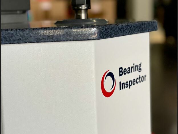
We chose to use a commercially available VIBRAC BRG-3000 Bearing Inspector II tabletop bearing torque measurement apparatus that we already owned and was readily available. Rather than modifying this apparatus to operate inside a cooled thermal chamber, we elected to design a small insulated chamber that would encapsulate the bearing and provide insulated mechanical connections between the apparatus and the interior of the small chamber. This allowed us to keep the test apparatus at room temperature.
The torque tester has a motor that is controlled by the VIBRAC software to turn a shaft connected to the inner ring of the bearing while the outer ring was restrained by the torque transducer that measures the reaction torque at the outer ring as the inner ring i turned in a controlled manner using the software provided with the testing apparatus.
The cold chamber was constructed using Schedule 40 polyvinyl chloride (PVC) with 25-cm (10-inch) diameter outer wall and 20-cm (8-inch) diameter inner wall with rigid 80-kg/m3 (5-lbm/ft3) PVC foam insulation between the walls. The top and bottom of the inner tube were capped by 3-mm (0.125-inch) thick aluminum discs counterbored into the end of the tube. For the upper and lower caps, 13-mm (0.5-inch) plates of aluminum were used. The plates were separated by a layer of rigid PVC foam 25-mm (1-inch) thick. An access door was cut through the walls and attached using a spring-loaded hinge and a latch.
Test Operation
During testing, the chamber was cooled using cold nitrogen gas injected tangentially through three nozzles inside the chamber. The cold gas was created by mixing room temperature nitrogen gas with liquid nitrogen.
The flow of the room temperature gas was adjusted manually to a desired constant flow rate using arotameter. The flow of the liquid nitrogen was controlled in an on/off fashion using a solenoid ball valve controlled thermostatically by a SOLO 9696 controller that was also readily available in our lab space.
During testing, we found that the flow of gas caused mechanical noise that was picked up by the sensitive torque transducer. Therefore, we temporarily turned off the flow of gas for a few seconds while taking a measurement. This worked quite well and allowed us to acquire reliable measurements of the starting torque.
The test apparatus was programmed to apply an angular acceleration of 0.050°/s2 up to an angular speed of 0.39°/s for 3° rotation tests and 0.50°/s for 5° rotation tests. This was adequate to measure the starting torque of the bearing as well as to overcome the wind-up in the torque transducer. For each bearing, three measurements were taken in the clockwise direction and three were taken in the counterclockwise direction.
Observations
During early testing, we observed some angular oscillation in the time history as the bearing started to turn. This led us to investigate in more detail how the torque transducer works internally rather than just treating it as a “black box.” Based on a diagram in the manual, we learned that the torque transducer principle of operation uses two rods acting collectively as a torsional spring connecting two disks. When torque is applied, one disk rotates a small amount relative to the other disk and the rods bend slightly. This relative rotational deflection is proportional to the applied torque, and is measured optically. It required about 0.5 deg of rotation to wind up this torsional spring before the torque reached the starting torque being measured.
The torque transducer was connected to the “fixed” outer ring with its deadweight disk. The small angular displacement of this “fixed” side led to a torsional pendulum action once the starting torque was overcome. For some operating conditions, the angular oscillations would feed back into the motor controller and the oscillations would continue. With a relatively large moment of inertia disk connected to a relatively soft torsional spring, the resonant frequency was just a few Hertz.
We learned to test with angular displacements below 5 deg and many tests were programed for 3 deg, so the apparent instabilty never amplified enough to cause any issues. We also learned to keep the commanded angular acceleration very low. This ensured that there were no dynamic effects during the wind-up leading to startup in which the two rings of the bearing started to move relative to one another. The maximum measured torque from the first peak was taken as the measured starting torque even if subsequent peaks were higher. This test apparatus is often used to measure continuous running torque and does not normally have a weight connected with a large moment of inertia, so we did not anticipate this effect prior to our testing. While it was interesting to observe this small dynamic effect, this motion all occured after the measurement of the starting torque.
Test Results
The results of the testing confirmed that the torque needed to overcome the resistance of the cold lubricant was significantly smaller than the driving torque available from the mechanism. The coldest anticipated operating temperature for the mechanism is -70°C. The qualification testing of the antenna will be performed at a lower temperature of -85°C to demonstrate adequate margin. However, the resisting torque measurements were performed down to -90°C and -100°C. Although it was apparent that the starting torque was increasing rapidly as temperature was lowered, even at -100°C there was still adequate torque margin to overcome the breakaway torque of the bearings.
Summary
Starting torque was measured at temperatures from 0°C to -90°C for two bearings and 0°C to -100°C for a third bearing. The oil selected is rated for operation down to -72°C and these measurements confirmed that the starting torque was quite consistent down to this temperature.
Since the expected operating temperature of these bearings during deployment of the radar antennas of the REASON instrument could be below the rated temperature, we measured starting torque down to lower temperatures. These measurements retired a risk that the oil might increase in viscosity and cause more bearing drag than the mechanism could overcome at low temperatures. This gives us confidence that the mechanisms will be able to perform as needed during qualification testing as well as in space during the Europa Clipper mission.
Acknowledgement
The research was carried out at the Jet Propulsion Laboratory, California Institute of Technology, under a contract with the National Aeronautics and Space Administration (80NM0018D0004).